Warrick Level Controls Troubleshooting
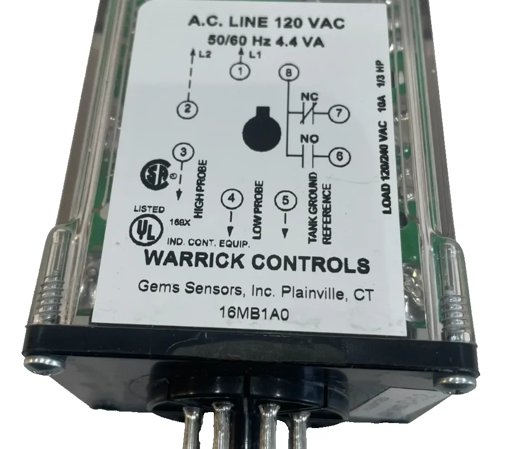
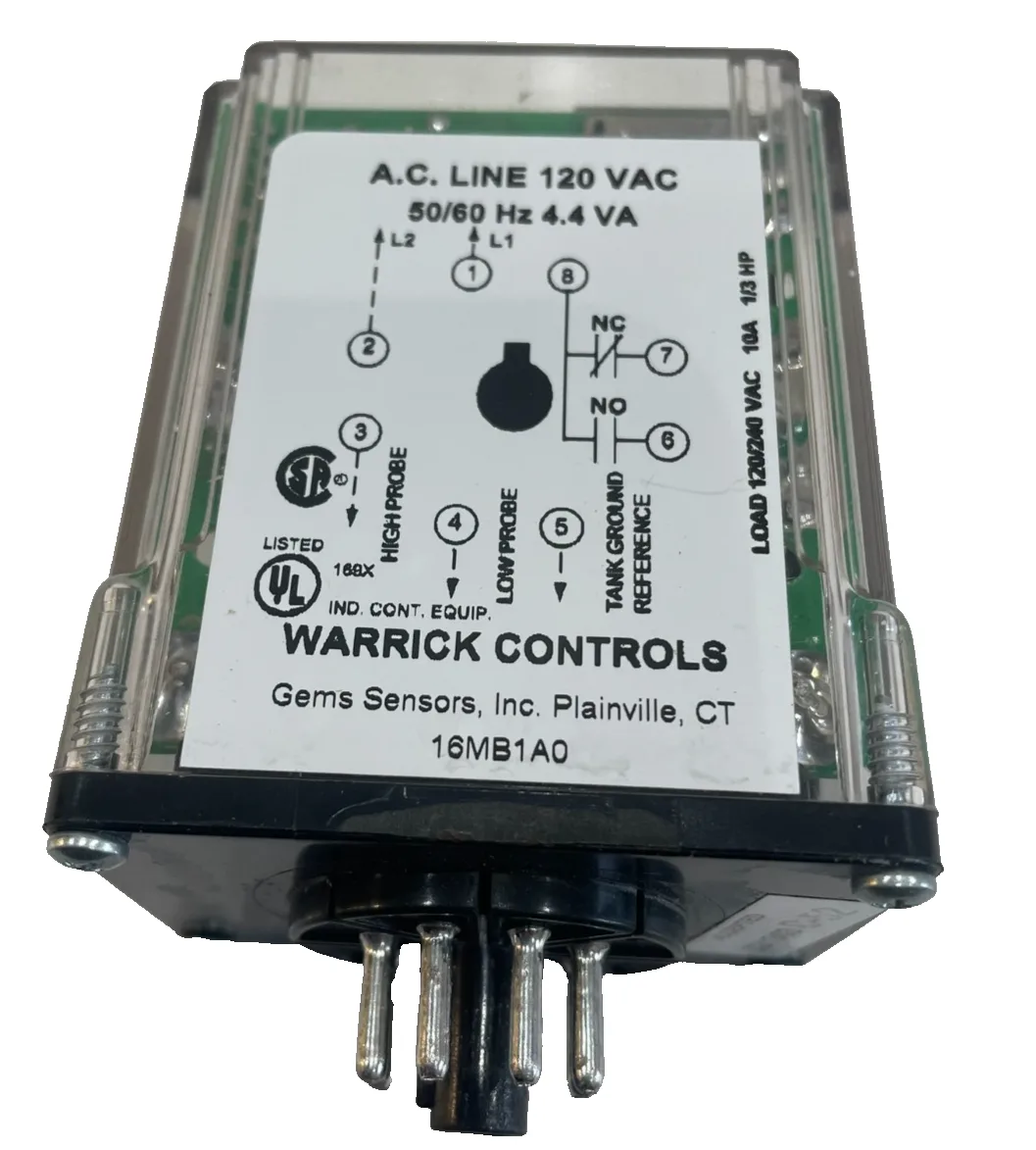
Image source: Bing (Web (fair-use with source credit))
Your boiler's low-water cutoff just tripped again. Or your sump pump ran dry because the level control let it keep pumping. If you're reading about Warrick Level Controls Troubleshooting, you're likely staring at a relay that won't behave, a tank that's overflowing, or a process that keeps shutting down.
You need a clear path to find the fault without chasing ghosts.
Warrick conductivity controls have been a workhorse in industrial fluid handling for decades. They sense liquid levels using the electrical conductivity of the fluid itself, with no floats, no moving parts in the tank, and a reliable relay output. Per manufacturer specifications, these controls can trip on conductivity as low as 20,000 ohms, making them extremely sensitive to probe condition and wiring integrity.
The problem is, that same sensitivity makes them vulnerable to false readings from scale, moisture, and cable issues. This guide walks you through the most common points of failure and how to fix them, step by step.
Quick Answer
Check power to the control relay first. Inspect and clean the probe tips. Test the relay by jumping the probe wires.
Verify liquid conductivity with a multimeter. Adjust sensitivity in small steps unless the liquid is very pure or conductive. Follow lockout/tagout before working on the equipment.
Why Getting Warrick Troubleshooting Right Matters
This is not a topic where guessing is acceptable. A misdiagnosed Warrick level control can lead to a boiler running dry, a chemical tank overflowing, or a lift station pump burning out from dry running. The financial cost of a single failure often exceeds the cost of a replacement control relay by a factor you do not want to discover the hard way.
The safety risks are even higher.
Let's start with the most common application: boiler protection. ASME CSD-1 requires automatic low-water fuel cutoffs on steam and hot water boilers. A Warrick conductivity probe is often the sensing element.
If that probe is coated with scale or the relay is miswired for fail-safe mode, the burner could keep firing with low water. The result can be catastrophic boiler damage, building evacuation, or worse.
The same principle applies to chemical sumps and wash tanks. Wrong sensor readings mean pumps run dry, expensive fluids overflow onto the floor, or downstream processes get flooded with the wrong liquid. The cost in cleanup, downtime, and lost product adds up fast.
In our research of maintenance forums and factory documentation, the most common underlying cause across all these scenarios is not a failed control relay. It's a dirty probe or a wiring issue. A proper troubleshooting method eliminates those simple problems first, before you start swapping parts.
So here is the framework that actually works. You follow it in order, and you don't skip steps. Doing so costs you time and can cause unnecessary equipment damage.
By the end of this article, you will know exactly how to diagnose a Warrick level control system, fix the most common problems yourself, and know when to call in a professional.
How Warrick Conductivity Controls Actually Work
You cannot fix what you do not understand. So let's break down the system into its three main components. The probe lives inside the tank.
The control relay mounts in an electrical panel. A length of cable connects them.
The probe is simpler than it looks. It's typically two or three stainless steel rods held in place by a threaded holder. Those rods are the sensing electrodes.
One rod might be a common reference (often the tank wall or a grounded pipe), and the other rod is the level sensor. A third rod can be a "low" or "high" reference for multi-point control.
Here is the key insight. These controls do not send a direct current through the liquid. They apply a small AC voltage, usually around 12 to 24 volts AC, between the probe rods.
This AC voltage prevents electrolysis and plating on the probe tips. When a conductive liquid touches both rods, the circuit is completed through the liquid. The control relay senses that completed circuit and changes its output state.
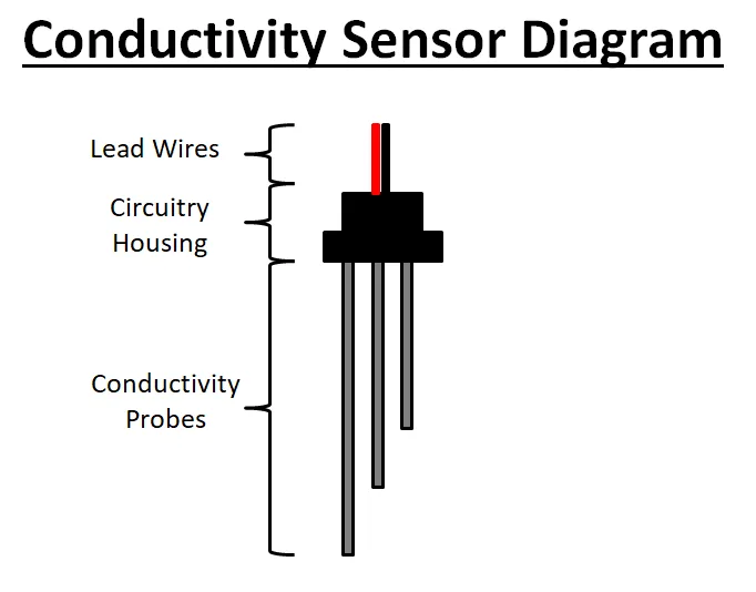
Image source: Bing (Web (fair-use with source credit))
The sensitivity dial adjusts the threshold at which the relay considers the circuit "on" or "off." You can think of it like a volume knob for conductivity. Turn the sensitivity higher, and the control will trip on a very weak circuit (high resistance, like pure water). Turn it lower, and it needs a strong circuit (low resistance, like dirty water or chemicals) to trigger.
The relay itself has two critical behaviors. When the probe circuit is completed, the relay "pulls in" and changes its contacts. When the circuit breaks, the relay "drops out" and returns to its resting state.
The difference between the pull-in point and the drop-out point is hysteresis, a built-in small gap that prevents the relay from chattering if the liquid level wobbles slightly.
Fail-safe mode is your safety net. Most Warrick controls have a jumper or DIP switch that selects between high-level fail-safe and low-level fail-safe. On low-level fail-safe, a loss of power or a broken probe wire causes the relay to de-energize, which stops the burner or starts the fill process.
On high-level fail-safe, the same failure causes the relay to de-energize, which would stop a pump from overflowing a tank.
Here's a common mistake: setting the fail-safe incorrectly for the application. Low-level fail-safe is the standard for boiler protection. You want a power loss to shut the burner off.
High-level fail-safe is typical for overflow protection on a condensate tank. Set it wrong, and a failure in the probe circuit could allow a dangerous condition to persist.
The final piece of the puzzle is the cable between probe and control. That cable has capacitance. In practice, a long run of unshielded wire can look like a weak circuit to the sensitive control, especially when the sensitivity dial is turned up high.
Manufacturer specifications advise using shielded cable for runs over 100 feet and warn that capacitance from long wire runs can cause false readings.
The Most Common Failure Symptoms and What They Mean
Every Warrick control failure falls into a small set of symptom patterns. This section gives you an if/then approach to identify the root cause quickly.
| Symptom | Likely Cause | First Check |
|---|---|---|
| Relay won't pull in at all | Probe not reaching liquid, broken probe wire, power loss to control, dead relay | Power at control, probe wiring continuity |
| Relay stays energized and won't drop out | Scale or deposits bridging probes, shorted probe wires, sensitivity set too high | Visual probe inspection, wire insulation check |
| Relay chatters or cycles rapidly | Marginal conductivity near the threshold, bad ground to tank, turbulence or foam | Sensitivity adjustment, ground connection, time delay setting |
| False high-level alarm | Foam bridging the probes, cable capacitance, scale buildup creating a constant conductive path | Cleaning probes, moisture check in cable, sensitivity reduction |
Let's dig deeper into each one.
Relay won't pull in. This is the most straightforward fault. If the relay is not pulling in, either the control is not getting power, the probe is not seeing the liquid, or the relay coil itself has failed. First, verify power at the control with a multimeter.
Then disconnect the probe wires from the control and temporarily jumper them together. If the relay pulls in with the jumper, the probe or wiring is the problem. If it still does not pull in, the control is the problem.
Relay stays energized. This is where things get tricky. If the relay stays on when the liquid level drops below the probe, you have a false circuit. The most common cause is a conductive scale or mineral deposit bridging the probe rods.
Boiler water, cooling tower water, and chemical solutions all leave deposits. Those deposits can create a path for the tiny sensing current even when the liquid is gone. Cleaning the probe tips is step one.
A shorted probe wire is step two. A sensitivity setting that is too high is step three.
Relay chatters or cycles rapidly. This symptom points to a borderline condition. The conductivity of the liquid is right at the threshold where the control is unsure. A bubble, a slight level change, or electrical noise can push it over the edge.
Drop the sensitivity a bit to add some headroom. If that helps, you probably had it set right at the edge. Also check that the tank or pipe is properly grounded.
A poor ground can cause the sensed circuit to fluctuate.
False high-level alarm. Foam is a notorious problem with Warrick controls. Foam is conductive enough to bridge the probe tips but does not represent a real high-level condition. If your application produces foam, you need a different probe arrangement or a time delay module.
Scale buildup can also create a constant false high level by connecting the probe rods through a crusty layer. Cleaning the probe and checking for cable moisture are the practical fixes for this one.
Your Step-by-Step Troubleshooting Process
Here is the order of operations. Follow it exactly. Do not skip steps.
Step 1: Lockout/Tagout and Safety Confirmation
Before you touch any control, turn off the power at the disconnect switch and apply your lockout. Confirm the power is dead with a meter at the control itself. Warrick controls operate on 120V, 240V, or 24V, depending on the model.
All of them can hurt you or cause arcing if you short the wrong terminals. OSHA 29 CFR 1910.147 requires this procedure for a reason. Do it.
Step 2: Visual Inspection
Now look at everything without disconnecting anything. Check the probe holder for cracks or signs of leaking. Look for moisture inside the conduit or terminal box at the probe.
Inspect the probe rods themselves. Are they heavily scaled or pitted? Check the control panel wiring.
Are the terminals tight? Are there signs of corrosion or burned insulation?
Step 3: Disconnect the Probe Wires and Jumper Test
This is your most powerful diagnostic move. Remove the two wires that go from the control to the probe. Temporarily twist their bare ends together or use a jumper wire to short them.
Power the control back on. Does the relay pull in? If yes, the control is functional, and the problem is in the probe or the cable.
If no, the control relay is likely dead or the power is not reaching it.
Step 4: Clean the Probe Tips
If the jumper test passed, turn power back off, remove the probe from the tank, and clean the probe rods. Use fine sandpaper or emery cloth to remove scale. For heavy mineral deposits, dip the probe tips in a mild acid solution like muriatic acid diluted 10:1 with water, then rinse thoroughly with clean water.
Never use a wire brush that can scratch the metal surface badly. Scratches create nucleation points for future scale.
Step 5: Check Liquid Conductivity
Fill a clean container with the actual liquid from the tank. Put the two multimeter probes into the liquid, spaced about the same distance as the Warrick probe rods. Measure the resistance.
If it is above the sensitivity range of your control (typically above 1 megohm), the liquid may simply not be conductive enough for this type of sensor. You might need a different control with a higher sensitivity setting or a different sensor technology.
Step 6: Verify Supply Voltage at the Control Coil
With power on, measure the voltage at the control's input terminals. It should be within 10% of the rated voltage. Low voltage can cause a relay to pull in weakly or not at all.
High voltage can damage the coil over time. A reading of 108 volts or 252 volts on a 120-volt or 240-volt system is a red flag.
Step 7: Adjust the Sensitivity Dial
If the relay pulls in with the jumper but not with the actual probe, and the probe is clean and the liquid is conductive, you likely need to adjust sensitivity. Turn the dial in small increments, clockwise to increase sensitivity (lower resistance threshold) or counterclockwise to decrease it. Do not turn it all the way in one shot.
Make a quarter-turn, test, and repeat.
Step 8: Re-test with Actual Liquid
Reinstall the clean probe. Fill the tank to the level where the control should trip. Watch the relay for stable operation.
Let the level drop below the probe. Does the relay drop out cleanly? Repeat the cycle a few times to ensure the control does not start chattering as the level approaches the probe.
Step 9: Document the Fix
Write down what the problem was and what you did to fix it. Note the sensitivity setting you ended up at. If the same control fails again in a few months, that documentation tells you something about the application, not a random failure.
Pro Tips for Adjusting Sensitivity Correctly
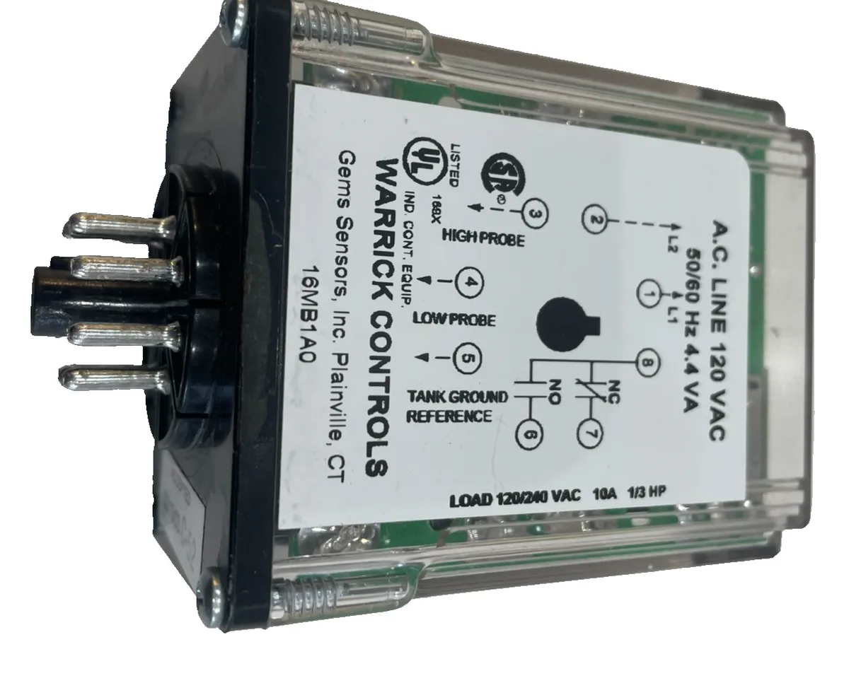
Image source: Bing (Web (fair-use with source credit))
Getting the sensitivity right is the difference between a reliable system and one that drives you crazy with false trips. Here is the nuance that most people miss.
Know your liquid's conductivity before you touch the dial. If you are working with boiler water, it is typically quite conductive due to dissolved minerals. You can set the sensitivity low. If the liquid is deionized water or a condensate, it has very low conductivity.
You need the sensitivity turned up high. If you set it too high on a conductive liquid, the smallest bridging of the probe by a drip or a bubble will trigger a false alarm.
Clockwise increases sensitivity. That means the control will trip on a higher resistance (weaker circuit). Counterclockwise decreases sensitivity and requires a lower resistance (stronger circuit). Check the control's faceplate for the correct direction, as a few older models were reversed.
Cable length matters more than you think. Every foot of wire adds capacitance between the conductors. Long cable runs can look like a weak conductive path to the control, especially at high sensitivity settings. If you have a run over 100 feet and are experiencing false readings, switch to shielded cable and connect the shield to the control's ground terminal.
If that does not fix it, you may need to reduce the sensitivity or relocate the control closer to the tank.
The number one mistake is overshooting the adjustment. Turn the dial too far clockwise in one move, and you will get false positives. The liquid that drains off the probe after the level drops will still be enough to keep the circuit complete for a moment. The result is a slow drop-out that looks like a stuck relay.
The fix is simple: back off the sensitivity by a quarter turn until the relay drops out promptly when the liquid recedes.
Use a time delay module for turbulent or foamy applications. Warrick offers time delay modules that mount inline with the probe or control. They add a short delay, usually 0.5 to 5 seconds, before the control responds to a level change. This prevents the relay from chattering due to sloshing, foam, or surface waves.
Set the time delay long enough to filter out noise but short enough to still provide real protection. A delay of 2 to 3 seconds is a good starting point for most tanks.
Pure water and high-purity chemical applications require special consideration. If your liquid is so pure that it hardly conducts electricity, a Warrick conductivity control may not be the right choice at all. In those cases, a capacitive or ultrasonic level sensor is usually more reliable. Check the manufacturer's data sheet for the minimum conductivity that your specific model requires.
It is usually stated in micromho/cm or resistance in ohms.
Common Installation Mistakes That Cause False Readings
Most false readings are not random failures. They are built in from day one by installation shortcuts. Here are the mistakes to avoid.
Probe spacing is wrong. If the probe rods are too close together, surface tension from a single droplet can bridge them and cause a false high. If they are too far apart, the probe may not sense the liquid at all, especially in low-conductivity fluids. Manufacturer guidelines typically recommend a gap of 1/4 to 1 inch between probe rods, depending on the liquid.
Check the installation manual for your specific model.
Using unshielded cable near power conductors. Running probe wires alongside motor leads, lighting circuits, or other high-current cables injects electrical noise into the sensing circuit. That noise looks like a fluctuating conductivity signal. The fix: run the probe cable in a separate conduit, and use shielded twisted-pair cable for any run over 50 feet.
Moisture in the probe housing or conduit. Water inside the terminal box at the probe creates a conductive path between terminals. This causes a permanent false high-level signal. Make sure the conduit entry is sealed with conduit compound or silicone.
Check the probe holder's gasket for cracks. Replace the O-ring if it has dried out.
Wrong fail-safe setting for the application. As mentioned earlier, setting the fail-safe jumper incorrectly can make the control unsafe. On a boiler low-water cutoff, always use low-level fail-safe so that a power loss or broken wire shuts the burner down. On an overflow protection application, use high-level fail-safe.
Double-check this before you close the panel.
Mixing control voltage from different phases. Warrick controls are line-voltage devices. If you pull the control voltage from one phase and the probe signal ground from another, you create a potential difference that can damage the control or cause erratic behavior. Always use the same phase and neutral for the control power and the probe circuit.
Not grounding the tank properly. The probe uses the tank wall or a dedicated ground rod as the reference electrode. If the tank is plastic or lined, you need a separate ground probe. Without a solid ground, the control cannot complete the sensing circuit reliably.
Use a dedicated ground rod immersed in the liquid at the same depth as the probe.
Maintenance Schedule for Reliable Operation
A little preventive maintenance goes a long way. Warrick controls are rugged, but they need attention.
Monthly visual check. Look at the probe holder and wiring from outside the tank. Any drips, corrosion, or signs of overheating? Check the terminal connections at the control panel for tightness.
A loose screw causes intermittent faults.
Quarterly cleaning. Remove the probe from the tank and inspect the rods. If there is any scale, sand them clean with fine sandpaper. In hard water applications, consider a quarterly dip in a mild acid solution as described earlier.
This prevents scale from building up to the point where it fools the control.
Semi-annual functional test. Simulate a high-level and low-level condition by raising and lowering the liquid level. Watch the relay pull in and drop out. It should do so cleanly with no chattering.
If it hesitates or flickers, clean the probe again and re-check the sensitivity.
Annual voltage check. Measure the supply voltage at the control terminals. Power quality can drift over time as transformers age or loads change. A nominal 120V line should read between 108V and 132V.
If it is outside that range, you have an electrical problem that can damage the control.
Seasonal considerations. Cold water is more conductive than hot water because lower temperature reduces ion mobility. If your process water temperature changes significantly between summer and winter, you may need to adjust the sensitivity dial seasonally. Mark the two positions on the dial with a paint pen so you can switch quickly.
When to Call a Pro or Replace the Unit
Not every problem is fixable with cleaning and adjustment. Here is when you need to replace components or bring in a qualified technician.
The control relay itself has failed. If the jumper test shows that the relay does not pull in even with the probe wires shorted, and you have verified power at the coil, the relay is dead. Burnt smell on the board, cracked housing, or visible burnt spots on the transformer are clear signs. Replacement relays are available from Gems Sensors & Controls and many industrial supply houses.
Make sure you match the exact model (Series 16, 16B, 16D, 17, etc.) because the wiring and fail-safe options differ.
Vacuum-tube era Series 16 units. If you have an old Warrick control with vacuum tubes, it is time to replace the entire unit. Those tubes are no longer manufactured, and the circuit boards are brittle. A modern solid-state replacement is safer, more reliable, and easier to troubleshoot.
The cost is modest compared to the risk of a failure.
Hazardous location requirements. If your tank is in a Class I Division 2 area (flammable vapors present), you need an intrinsically safe barrier between the probe and the control. Standard Warrick controls are not rated for hazardous locations without this barrier. If you see a label indicating "IS" on the control, that model is already intrinsically safe.
If not, do not install a standard unit in a hazardous area without the proper barrier. Consult a licensed electrician.
Legal and code requirements. Boiler low-water cutoffs are regulated under ASME CSD-1 and NFPA 85. Any modification to the control system must maintain compliance. If you are replacing a failed unit, use a model that is UL 353 listed for limit controls.
If you are uncertain about the code requirements for your installation, call a boiler service professional.
The probe is damaged beyond cleaning. If the probe rods are pitted, bent, or broken, replace them. Probe assemblies are relatively inexpensive. Do not try to weld or patch a damaged probe.
The weld can create a poor electrical connection and cause erratic sensing.
Frequently Asked Questions
Why is my Warrick control picking up foam as a high level?
Foam is conductive enough to bridge the probe rods. The control sees it as liquid and triggers the alarm. Solutions include lowering the sensitivity, moving the probe higher above the foam layer, or installing a time delay module that ignores brief contacts.
Can I use a Warrick probe in a chemical tank?
Yes, if the probe material is compatible. Standard probes are 316 stainless steel, which resists many chemicals. For highly corrosive liquids, use Hastelloy or graphite probes.
Always check the chemical compatibility chart from the manufacturer before installation.
What's the maximum cable length between probe and relay?
Manufacturer specs allow up to 1,000 feet with shielded cable for most models. For runs over 100 feet, use shielded twisted-pair cable and connect the shield to the control's ground terminal. Longer runs increase capacitance and can cause false readings at high sensitivity settings.
How often should I clean my level-control probes?
For hard water or scaling applications, clean the probes every three months. For clean water or non-scaling liquids, once a year is usually enough. If you see a gradual drift in the level reading, that is a sign the probe needs cleaning sooner.
My Warrick relay clicks but won't hold — what's wrong?
The relay is momentarily pulling in but dropping out immediately. This usually means the liquid conductivity is borderline. The control senses the circuit and then loses it.
Lower the sensitivity setting slightly. If that does not fix it, check the probe for partial bridging by scale or debris.
Does liquid temperature affect conductivity readings?
Yes, temperature affects conductivity. Hot liquids are more conductive than cold ones because ions move faster. If your process water temperature varies widely, you may need to adjust sensitivity seasonally.
Some newer controls have temperature compensation, but most Warrick units do not.
Can I test a Warrick control without water in the tank?
Yes. Disconnect the probe wires and short them with a jumper wire. The relay should pull in immediately.
That confirms the control itself is good. Remove the jumper and the relay should drop out. This test works as long as the control has power.
What's the difference between Series 16, 16B, and 16D?
Series 16 is the original control. Series 16B added a built-in time delay option. Series 16D has dual-channel capability for two independent probes.
All share the same basic operating principle, but wiring and adjustments differ. Always use the model-specific manual when troubleshooting.
Where is the fail-safe jumper on my Warrick control?
On most models, the fail-safe jumper is a small plastic shunt on the circuit board, near the terminal block. It may be labeled "H/L" for high/low. On older units, it is a wire jumper between specific terminals.
Check the wiring diagram on the inside of the control cover.
Is there a universal replacement if my Warrick relay is discontinued?
Several control manufacturers offer universal replacement relays that work with standard two-probe and three-probe systems. For example, the Gems Series 17 and Neptune series controls are common drop-in replacements. Verify that the replacement has the same fail-safe options, voltage rating, and time delay features as your original.

Similar Posts