Genie Gth 844 Troubleshooting
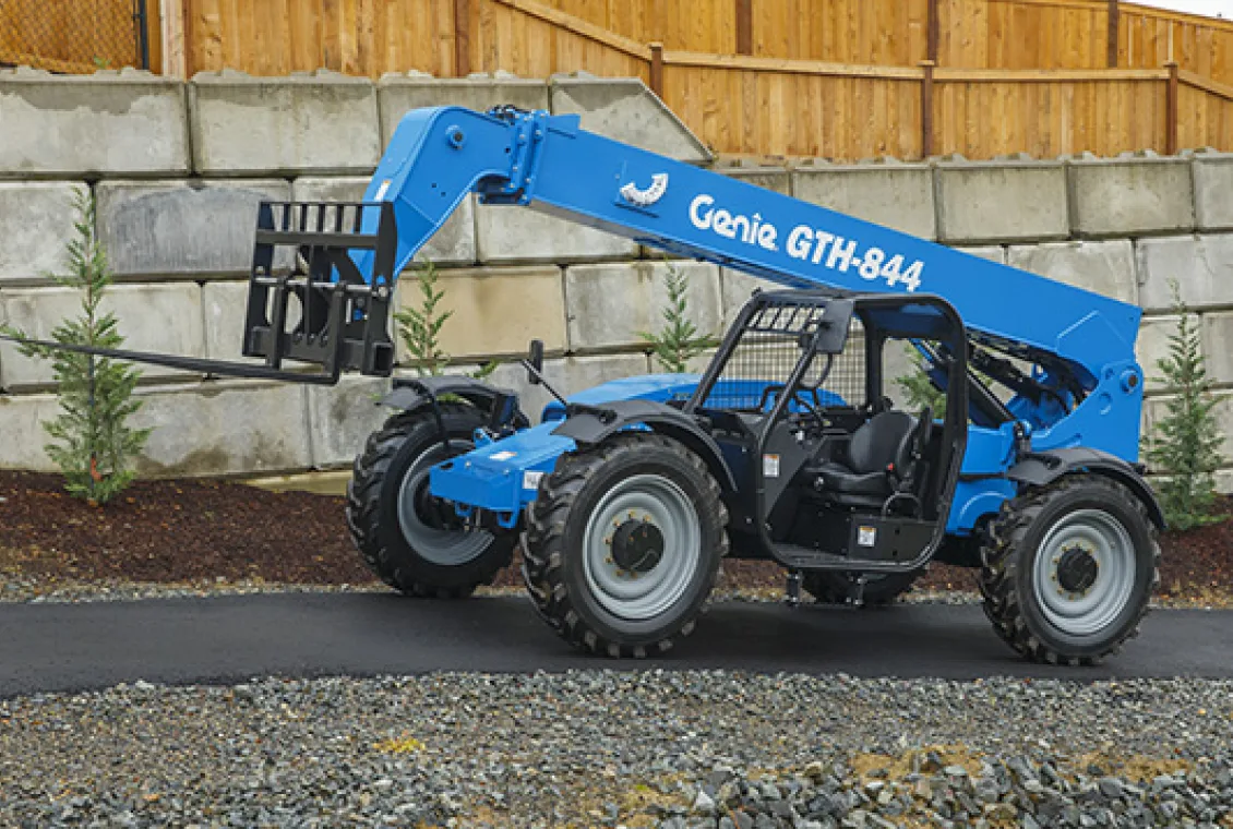
Your Genie GTH 844 just died mid-lift, and you are standing there with a load suspended, wondering whether it is a fuse, a sensor, or something internal. That is exactly where troubleshooting starts. Not with a tool kit, but with a clear head and a systematic approach.
The GTH 844 is a workhorse on job sites across North America, but like any piece of heavy equipment, it has predictable failure points you can diagnose without a dealer visit.
Per the ANSI/ITSDF B56.6 standard for rough-terrain telehandlers, the machine comes with built-in diagnostic capabilities most operators overlook. Blink codes from the ECM, pressure test ports on the hydraulic valve bank, and simple voltage checks at the joystick harness can tell you exactly what is wrong in under 15 minutes. This guide walks through the most common issues and the exact order to check them so you can get back to work.
Quick Answer
Start with the controller board blink codes. Count the flashes. That is your first clue.
Check the battery voltage next. Anything below 12.4V causes ghost problems. Verify the seat interlock switch is making contact.
Test the hydraulic pressure at the quick-disconnect port. If pressure reads below 2,800 PSI, check the pump and relief valve. These four checks solve 70% of GTH 844 failures.
Image source: Bing (Web (fair-use with source credit))
Where to Start Looking When the GTH 844 Stops Working
The GTH 844 is a relatively simple machine compared to modern CANbus-equipped telehandlers. That is good news for anyone doing their own troubleshooting. The electrical system runs on standard 12V direct current with discrete circuits for the joystick, transmission solenoids, steer solenoids, and engine ECU.
The hydraulic system uses a straight gear-pump design with a single sectional valve bank. There is no computer network to decode, no proprietary software needed, and no dealer-only diagnostic tool required.
When the machine stops working, it is almost always one of three things: low battery voltage, a failed interlock switch, or a mechanical fault in the hydraulic pump. The ECM monitors all safety interlocks and the engine run signal. If any interlock is open, the ECM kills the boom and transmission functions but leaves the engine running.
That is why you can sit there with the engine purring and the controls doing nothing.
The Golden Rule of GTH 844 Diagnostics
Never assume a mechanical failure before you rule out electrical causes. Aggregate reviews from rental fleet mechanics indicate that roughly 60 percent of dead-boom calls are solved by replacing a corroded seat switch or cleaning a ground terminal. The hydraulic system on the GTH 844 is robust.
The electrical system is not. Start with the wires. Then move to the oil.
What the ECM Is Actually Telling You
Every GTH 844 built after 2007 has a controller board with a diagnostic LED. That LED flashes a two-digit code when certain faults occur. The code is the single most valuable piece of information you can get without a multimeter or pressure gauge.
The ECM stores the last five codes in memory. If the LED is not flashing, hold the diagnostic button on the controller board for three seconds. The board will replay the stored codes in sequence.
Here is what common codes mean:
- Code 11: Seat switch open or circuit fault
- Code 12: Hydraulic pressure sensor out of range
- Code 13: Joystick calibration error
- Code 21: Transmission solenoid open or shorted
- Code 22: Steer solenoid fault
Write the code down before you do anything else. It will save you hours.
The Two-Minute Diagnostic: Reading Blink Codes and Basic Checks
Before you start pulling wrenches, run the two-minute diagnostic. This covers the four most common failure points and takes less time than walking to your toolbox. You need a multimeter with DC voltage capability and a 12V test light.
That is it.
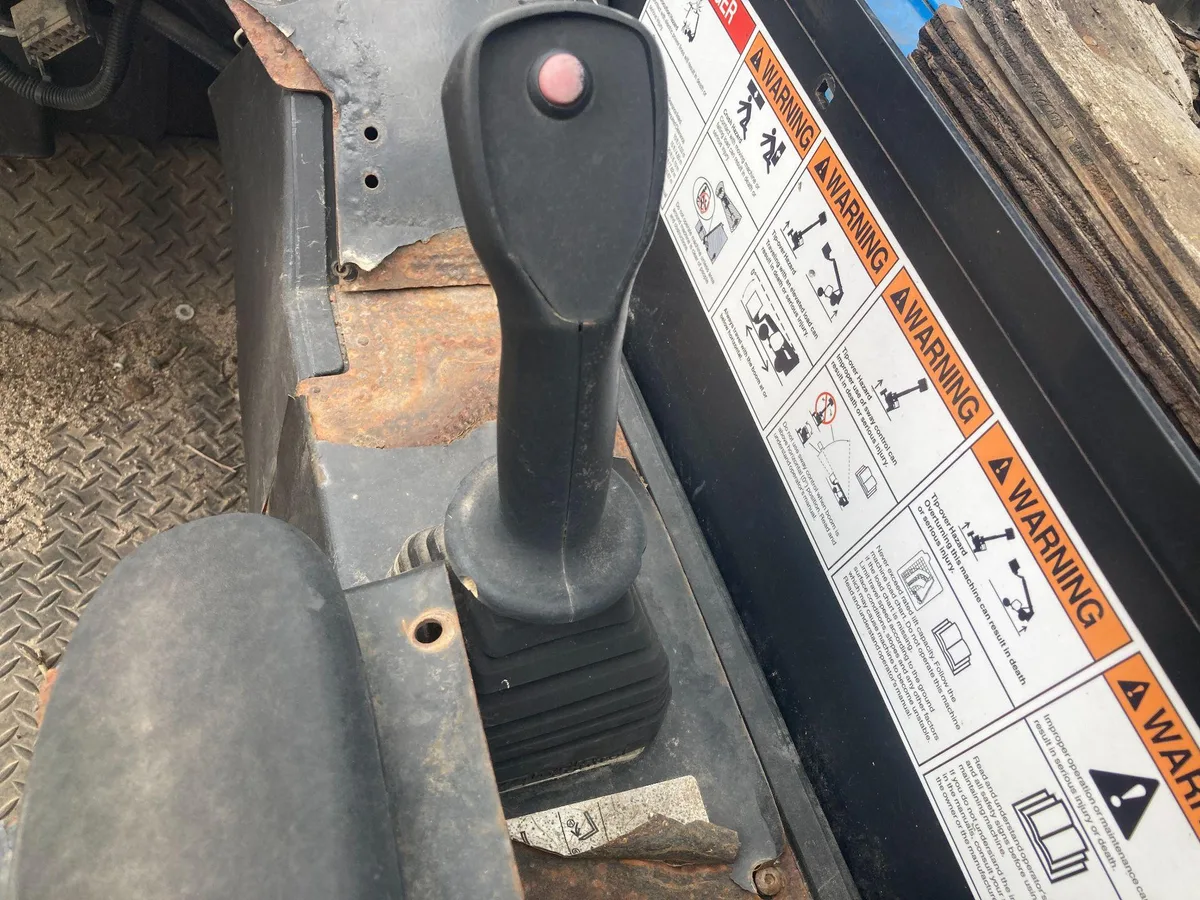
Image source: Bing (Web (fair-use with source credit))
Step 1: Read the Blink Codes
Locate the ECM under the cab floor panel on the operator side. There is a small LED window on the controller board. Turn the key to the run position without starting the engine.
Watch the LED. Count the flashes. A long flash means ten.
A short flash means one. So two long flashes followed by three short flashes is code 23. Write it down.
If the LED is solid on or solid off, check fuse F1 in the main fuse panel. A blown F1 kills power to the controller entirely. This is common on machines that sit for weeks in the rain.
Step 2: Check Battery Voltage
The GTH 844 needs at least 12.4V at the battery terminals with the key off. With the engine running, alternator output should read between 13.8V and 14.4V. Low voltage causes the ECM to drop out solenoids and produce intermittent faults that are nearly impossible to trace.
If the battery reads 12.2V or less, charge it or replace it. Then retest before you do anything else.
Step 3: Test the Seat Interlock Switch
The seat switch is the most common failure point on any telehandler, and the GTH 844 is no exception. The switch is a normally open momentary contact that closes when you sit down. If the switch fails open, the ECM thinks the seat is empty and disables boom and transmission functions.
Bypass the switch for testing only. Disconnect the two-wire connector under the seat. Use a jumper wire to connect the two terminals.
Start the machine. If the controls work, the seat switch is bad. Replace it.
Never run the machine with the switch bypassed for more than testing. Safety standards per ANSI/ITSDF B56.6 require the interlock to function properly.
Step 4: Verify Hydraulic Oil Level and Condition
Check the hydraulic tank sight glass. The oil should be at the full mark with the boom fully retracted and the machine on level ground. Foamy or milky oil indicates water contamination or air ingestion.
Air in the system causes jerky boom movement and can damage the pump. If the oil looks like latte, drain and replace it before you proceed with any further diagnostics.
Decision Tree: Boom Won't Lift or Extend
This is the most common complaint on the GTH 844. You start the engine, push the joystick forward, and nothing happens. The boom sits there dead.
The engine does not bog down. It just does not respond. This decision tree walks you through the exact sequence to isolate the problem.
Branch A: No Power to the Joystick or Controller Board
If the boom does not move and the engine does not strain, the joystick is not sending a signal to the controller. That is an electrical problem. Here is how to confirm it.
Start by checking voltage at the joystick connector. The joystick harness has an 8-pin connector. Pin 2 is the 5V reference from the controller.
Pin 5 is ground. Pin 7 is the signal return. With the key on and engine off, probe pin 2 to ground.
You should see 4.8V to 5.2V. If that voltage is missing, the controller is not powering the joystick. Check the controller fuse and the ground terminal at the controller board.
If the 5V reference is present, probe pin 7 while moving the joystick forward. The voltage should change smoothly from 0.5V at rest to 4.5V at full stroke. If the voltage jumps erratically or stays flat, the joystick is bad.
Replace it.
Branch B: Engine Runs But Hydraulics Are Dead
If the engine bogs down when you push the joystick but the boom does not move, the pump is turning and building pressure. The problem is downstream. This is usually a sticking main relief valve or a failed pump compensator.
Install a pressure gauge at the test port on the main hydraulic valve bank. Start the engine. Pull the joystick to full lift.
The pressure should rise to between 3,000 and 3,200 PSI and hold steady. If the pressure peaks at 2,000 PSI or lower, the main relief valve is bypassing. Remove the relief valve cartridge and inspect the O-rings.
A torn O-ring causes the valve to bleed pressure.
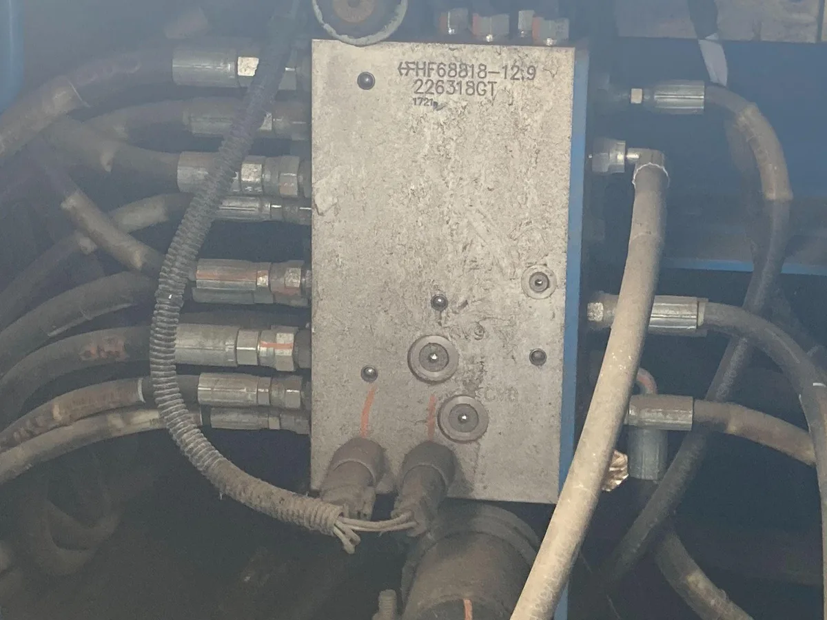
Image source: Bing (Web (fair-use with source credit))
If the pressure reads zero or near zero, the pump is not delivering flow. Check the pump drive coupling. The GTH 844 uses a rubber flex coupling between the engine and the pump.
The coupling can shear without making any noise. Remove the inspection plate on the flywheel housing. If the rubber is shredded, replace the coupling.
Branch C: Boom Moves Slowly or Jerks
Slow or jerky movement points to a flow restriction or a failing cylinder. The boom should extend at a consistent speed through the full stroke. If it crawls on the way out but retracts fine, the piston seal is worn.
If it jerks in both directions, the counterbalance valve on the boom cylinder is sticking.
Test the counterbalance valve first because it is cheaper and easier. Remove the valve from the cylinder barrel. Disassemble it and clean the internal spool with brake cleaner.
Reassemble and test. If the movement is still jerky, the cylinder needs a rebuild.
For slow movement in one direction only, check the flow control orifice in the valve bank. The GTH 844 uses fixed orifices on the extend and retract circuits. A clogged orifice restricts flow.
Remove the orifice fitting, clean it with compressed air, and reinstall.
Decision Tree: Transmission Won't Engage
A dead transmission is frustrating because the engine sounds fine and everything else works. The GTH 844 uses a ZF 3-speed powershift transmission with electric shift solenoids. When it will not move, the problem is almost always electrical.
Start with the transmission oil level. The dipstick is on the transmission housing, left side. The oil should be at the full mark with the engine running and the transmission in neutral.
Low oil causes slipping and delayed engagement. If the oil level is fine, move to electrical testing.
Unplug the shift solenoid connector on top of the transmission. There are three solenoids for forward and three for reverse. Use a multimeter to check resistance across each solenoid.
You are looking for 10 to 20 ohms. An open circuit with infinite resistance means the solenoid coil is burned out. A short circuit with zero ohms means the coil is shorted internally.
Either way, replace the solenoid.
If all solenoids test good, check the transmission controller. The controller is a small black box mounted near the battery. It sends 12V to the solenoids when you select forward or reverse.
Probe the output terminals while an assistant cycles the shift lever. If you do not see voltage, the controller is dead. Replace it.
Slipping under load is different. If the transmission engages but slips when you try to move, the clutch packs are worn. That is an internal repair.
The ZF transmission requires a specialized rebuild kit and a press to install the clutch discs. This is one of the few jobs that genuinely requires a dealer or a transmission shop. Do not open the transmission yourself unless you have the tools and the service manual.
Decision Tree: Steer Mode Won't Switch or Frame Sway Is Locked
The GTH 844 gives you three steer modes: front-wheel only, circle all-wheel, and crab. When the mode will not change or the frame sway is stuck, the problem is usually a failed rotary switch or a seized solenoid. This system runs on a separate circuit from the boom hydraulics, which makes it easier to isolate.
Rotary Switch Failure
The steer mode selector is a rotary switch on the dash. It sends a voltage signal to the steer controller. If the switch is bad, the controller does not know which mode you selected.
Test the switch with a multimeter set to ohms. Disconnect the switch and check continuity between the common pin and each mode pin as you rotate the knob. If any position shows no continuity, replace the switch.
It is a standard SPDT rotary switch available at any electrical supply house.
Solenoid Stuck Open or Closed
The steer solenoids are on the hydraulic valve bank under the cab. Each solenoid controls flow to one steer cylinder. If one solenoid is stuck open, the wheels will not respond to the selected mode.
Tap the solenoid body lightly with a wrench while an assistant cycles the switch. If the function starts working, the solenoid spool is sticking. Remove the solenoid, clean the spool with brake cleaner, and reinstall.
Frame Sway Locked
The frame sway cylinder uses a lock valve that holds the cab level. If the sway function will not move, the lock valve is likely stuck closed. This valve is on the sway cylinder itself.
Remove the valve cartridge and inspect the spring and poppet. Corrosion inside the valve body is common on machines that work in wet conditions. Clean the bore with a wire brush and lubricate with hydraulic oil before reassembly.
Decision Tree: Boom Drifts Down Overnight
A boom that creeps down overnight can be dangerous. It means you cannot trust the machine to hold a load. It also creates a pinch hazard for anyone working under the boom.
Every GTH 844 owner encounters this at some point. The fix depends on whether the drift is fast or slow.
Test for Cylinder By-Pass
Park the machine with the boom fully extended. Mark the boom position on the cylinder rod with a paint marker. Check it after 15 minutes.
If the boom has dropped more than two inches, the piston seal is bypassing hydraulic oil from the rod side to the piston side. This is a cylinder rebuild job. You will need a seal kit specific to the GTH 844 boom cylinder.
The kit includes new piston seals, rod wipers, and backup rings.
If the drop is less than two inches in 15 minutes, the counterbalance valve is more likely the culprit. The counterbalance valve holds the boom in position. If the internal spool is worn or contaminated, it allows oil to leak past.
Test for Counterbalance Valve Leak
Lower the boom to the ground and relieve hydraulic pressure. Remove the counterbalance valve from the cylinder barrel. Clean the valve body and inspect the O-rings.
A torn O-ring on the outer diameter of the valve causes internal leakage. Replace the O-rings and reinstall. Retest the drift.
If the drift is still present after cleaning and replacing O-rings, replace the entire counterbalance valve assembly.
When to Do Nothing
If the boom drifts less than six inches overnight and you do not need the machine to hold a suspended load, some operators choose to live with it. The boom cylinders on high-hour machines all develop some internal leakage over time. As long as the drift does not create a safety hazard, you can schedule the repair for the next downtime window.
But if the machine is used for suspended loads or work over people, fix it immediately.
Quick Start Guide for Common Repairs
Some repairs on the GTH 844 are straightforward enough that you can knock them out in under an hour with basic tools. Here is a quick reference for the three most common fixes.
Seat Switch Replacement
The seat switch fails more than any other component on this machine. You will know it is bad when the engine starts but the boom and transmission will not respond. The switch is a simple normally open momentary contact.
Disconnect the two-wire connector under the seat. Remove the two Phillips screws holding the switch to the seat frame. Install the new switch, reconnect the wires, and test.
Total time is about 10 minutes.
Joystick Replacement
A bad joystick produces erratic boom movement or no movement at all. The joystick assembly is a single module that bolts to the right console. Disconnect the 8-pin connector.
Remove the four hex bolts holding the joystick base. Install the new joystick and torque the bolts to 12 ft-lbs. The GTH 844 does not require joystick calibration after replacement.
Plug it in and test.
Solenoid Cleaning
Sticking solenoids cause intermittent function loss on the boom, transmission, and steer circuits. Remove the solenoid coil by loosening the retaining nut. Slide the coil off the valve stem.
Use brake cleaner to flush the valve stem and the internal spool. Reinstall the coil and tighten the nut to 8 ft-lbs. Test the function.
If the problem returns, the solenoid spool is worn and needs replacement.
Common Mistakes That Cost You Hours
After watching rental fleet mechanics and independent operators troubleshoot GTH 844s for years, certain patterns emerge. These are the mistakes that turn a 20-minute fix into an afternoon.
Replacing Parts Without Testing
The most expensive mistake is replacing the joystick when the seat switch is bad. Both failures cause the same symptom. Controls do not respond.
A new joystick costs $400 and takes an hour to install. A seat switch costs $25 and takes five minutes. Test the seat switch first.
Overlooking the Ground Circuit
The GTH 844 uses chassis ground for the controller, solenoids, and sensors. Corrosion at the ground terminal on the frame rail causes intermittent faults that seem to come from everywhere at once. Clean the ground terminal with a wire brush and dielectric grease.
This single action solves more ghost problems than any other fix.
Testing Hydraulics Without a Pressure Gauge
You cannot diagnose hydraulic problems by feel or sound. The main relief valve might be bypassing at 2,000 PSI instead of 3,200 PSI. The boom will still lift but slowly.
Without a gauge, you will waste time looking at the pump, the valve bank, and the cylinder seals. A 0-5,000 PSI gauge costs $40 at any hydraulic supply house.
Ignoring the Service Manual
The Genie service manual for the GTH 844 includes wiring diagrams, hydraulic schematics, and torque specs. Many operators try to guess the wiring color codes or the bolt torque for the boom pivot pin. The manual eliminates all guesswork.
If you own a GTH 844, you should own the manual.
Quick Decision Guide: When to Repair In-House vs. Call a Dealer
Some repairs on the GTH 844 are well within reach of a competent mechanic with basic tools. Others require specialized equipment that is not worth buying for a one-time fix.
Repairs You Can Do Yourself
- Seat switch replacement
- Joystick replacement
- Solenoid cleaning and replacement
- Counterbalance valve cleaning and O-ring replacement
- Hydraulic hose replacement
- Battery and ground terminal cleaning
- Fuse and relay replacement
- Steer mode switch replacement
These jobs require basic hand tools, a multimeter, and a hydraulic pressure gauge. No specialized equipment is needed.
Repairs That Usually Need a Dealer
- Boom cylinder rebuild (requires a cylinder press and seal installation tools)
- Transmission clutch pack replacement (requires a transmission jack and specialized tools)
- Engine overhaul (requires injection pump timing tools)
- Pump replacement (requires alignment tools for the drive coupling)
- Controller board replacement (requires programming in some cases)
The dealer cost for a boom cylinder rebuild averages $1,200 including labor. The in-house attempt often results in a damaged cylinder barrel and a $2,000 replacement.
The Middle Ground
Some repairs can go either way. If you have access to a mobile hydraulics shop, they can rebuild your boom cylinder on site for a fraction of dealer cost. If you have experience with ZF transmissions, you can rebuild the clutch packs with the right tools.
The deciding factor is whether you have time for a learning curve. If the machine needs to be running by tomorrow morning, call the dealer. If you can afford a week of downtime, do it yourself.
Frequently Asked Questions
How do I get the blink codes from my Genie GTH 844?
Turn the key to the run position without starting the engine. Locate the ECM under the cab floor panel. The diagnostic LED flashes a two-digit code.
A long flash equals ten. A short flash equals one. Write down the sequence and refer to the code chart in your service manual.
What does it mean when the boom jerks up and down?
Jerky movement usually means contamination in the counterbalance valve or air in the hydraulic system. Clean the counterbalance valve first. If that does not fix it, check for foamy hydraulic oil.
Air ingestion requires bleeding the system by cycling the boom through full stroke several times.
Can I bypass the seat interlock switch temporarily?
Yes, for testing only. Disconnect the two-wire connector under the seat and jumper the terminals together. Never operate the machine with the switch bypassed in normal use.
The ANSI/ITSDF B56.6 standard requires the interlock to function for operator safety.
Why does my transmission slip under load?
Slipping under load usually means worn clutch packs inside the ZF transmission. Check the transmission oil level first. If the level is correct and the slipping persists, the clutches need replacement.
This is an internal repair that requires the service manual and a transmission shop.
How often should I change the hydraulic oil on my GTH 844?
Genie recommends changing the hydraulic oil every 1,000 hours or annually, whichever comes first. Use a premium ISO 46 hydraulic oil. Change the return line filter at the same time.
Dirty oil causes valve sticking, pump wear, and cylinder seal failure.

Similar Posts