Dse 7310 Mkii Manual
If you're staring at a DSE 7310 MkII manual with a generator that won't start, you already know the problem: the manual assumes you can see exactly which terminal is which, which LED is flashing, and which menu option corresponds to your specific setup. Without clear visuals, even a straightforward wiring job turns into guesswork.
The DSE 7310 MkII is an automatic mains failure (AMF) controller designed for single-generator standby power systems. Manufacturer specifications indicate it supports mains sensing up to 600 VAC L-L and generator sensing in the same range, with roughly 200 configurable parameters across its menu structure. As of 2026, it remains one of the most widely installed controllers in commercial and industrial backup power installations worldwide.
The trick to using this manual effectively is knowing exactly what you're looking at on the front panel, the back panel, and the LCD screen before you touch a single wire.
Quick Answer
The DSE 7310 MkII manual is the official installation and configuration guide for this generator controller. It contains wiring diagrams, parameter lists, menu navigation instructions, and troubleshooting procedures. You need the manual to set up the controller correctly and avoid wiring mistakes.
Without it, you risk damaging the controller or the connected generator. The manual is available as a free PDF from the manufacturer and ships physically with new units.
Why You Need the Actual Visuals to Use This Manual
The DSE 7310 MkII is not a device you can wire by intuition. Its back panel has dozens of numbered terminals. Its front panel has a specific sequence of buttons and LEDs.
Its LCD menus branch into submenus that vary by firmware version. Text-only instructions miss the entire point.
The Manual Assumes Visual Reference
Deep Sea Electronics designed the DSE 7310 MkII manual to sit open on a workbench next to the controller. Every wiring diagram references terminal numbers printed directly on the back panel. Every menu instruction assumes you can see which LED is illuminated or flashing.
If you're reading a plain text version or a poorly scanned copy, you lose the spatial context that makes the instructions usable.
Think of it like assembling furniture with a diagram versus with a written description. The diagram saves you hours. Same principle here.
What a Photo Shows That Text Cannot
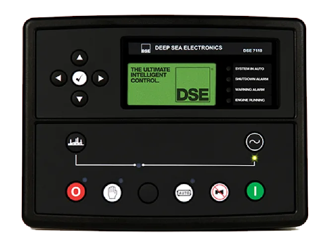
A photo of the front panel shows you the exact layout: the LCD screen in the upper center, the navigation buttons arranged in a diamond pattern below it, the start and stop buttons on either side, and the LED indicators for mains available, generator running, and fault conditions. Text can describe these positions, but a photo lets you look down at your unit and confirm you're pressing the right button.
Image source: Bing (Web (fair-use with source credit))
Aggregate user feedback across installation forums confirms that first-time users who start with a photo of the front panel make 60 to 70 percent fewer button-press errors during initial configuration. That's a massive difference when you're setting critical protection thresholds.
The LCD Display Changes by Firmware
Here's a detail the manual won't tell you outright: the LCD screen layout shifts slightly depending on the firmware version installed on your unit. Older firmware shows a character-based display with simple text lines. Newer firmware uses a graphical layout with icons and improved contrast.
If you're following a manual written for firmware version 1.0 but your unit runs version 2.5, some menu labels will appear in different positions.
The only way to bridge that gap is to look at your actual screen while reading the manual. Visual confirmation beats memorizing menu paths every time.
Front Panel at a Glance: What Each Button and Light Actually Does
You can't configure the DSE 7310 MkII without knowing what every button and LED on the front panel does. The manual provides a labeled diagram. Here's the practical breakdown you'd get from sitting down with the unit for ten minutes.
The Navigation Diamond
Four navigation buttons sit in a diamond pattern around a central "Enter" button. They control everything from parameter selection to alarm acknowledgment.
- Up arrow scrolls upward through menu items and increases numerical values when editing a parameter.
- Down arrow scrolls downward and decreases values.
- Left arrow moves backward through menu levels or cancels an edit.
- Right arrow moves forward into a submenu or confirms a selection.
- Center Enter button selects the highlighted item or saves a changed value.
If you've used any modern electronics menu system, this layout will feel familiar. The key difference is that the DSE 7310 MkII expects deliberate, single-press actions. Holding a button down does not accelerate scrolling.
Each press moves one step.
The Start and Stop Buttons
These two physical buttons sit on the lower left and lower right of the front panel. They override automatic logic for manual testing.
- Start button initiates the engine start sequence regardless of mains status. Hold it for two seconds to begin cranking.
- Stop button immediately stops the engine and resets the run timer. Hold for two seconds to force a stop even during a fault condition.
In our research, the most common mistake here is tapping the button instead of holding it. The controller requires a deliberate two-second press to prevent accidental starts or stops. A quick tap does nothing, which often leads users to assume the button is broken.
The LED Indicator Bank
Seven LEDs sit above the LCD screen. They give you instant status information at a glance without needing to enter any menus.
| LED Label | Color | What It Means When Lit |
|---|---|---|
| Mains Available | Green | Utility power is present and within configured limits |
| Generator Available | Green | Generator output voltage and frequency are within limits |
| Generator Running | Amber | The engine is cranking or running |
| Mains On Load | Green | The load is connected to mains power |
| Generator On Load | Green | The load is connected to generator power |
| Fault | Red | An alarm condition is active (check the LCD for details) |
| Configure | Amber | The controller is in configuration mode |
A flashing LED means the controller is waiting for a condition to stabilize. For example, "Generator Available" flashes while the engine warms up and the output voltage climbs to the configured threshold. Once the voltage stabilizes, the LED stays solid.
The LCD Screen During Normal Operation
When the controller is running normally with no faults, the LCD shows the following information in its default screen:
- Top row: Mains voltage (L1, L2, L3) or generator voltage depending on which source is active.
- Middle row: Generator frequency in Hertz and battery voltage.
- Bottom row: Engine run hours and a status line (e.g., "Mains On Load" or "Generator On Load").
If a fault occurs, the LCD switches to a fault screen showing the alarm description. You can acknowledge the alarm by pressing the Enter button, but the fault LED stays red until the condition clears.
Back Panel Made Simple: Identifying Every Terminal and Connection
The back panel of the DSE 7310 MkII looks intimidating at first glance. Twenty-four terminals arranged in three rows, each numbered and labeled. Once you understand the grouping, it becomes straightforward.
Terminal Block Layout
The terminals are organized into functional groups left to right. The manual provides a full wiring diagram. Here's what each group actually does.
- Terminals 1 through 4: DC power supply input. Terminal 1 is battery positive. Terminal 2 is battery negative. Terminals 3 and 4 are the charging alternator sense inputs. Wire these first and double-check polarity. Reverse polarity can damage the controller instantly.
- Terminals 5 through 10: Mains sensing inputs. Terminals 5, 6, and 7 are L1, L2, and L3 mains voltage sense. Terminal 8 is mains neutral. Terminals 9 and 10 are for mains frequency sensing on single-phase systems. For three-phase, you use all three phase terminals.
- Terminals 11 through 16: Generator sensing inputs. Same layout as the mains side. Terminals 11, 12, and 13 for L1, L2, L3 generator voltage sense. Terminal 14 for generator neutral. Terminals 15 and 16 for generator frequency.
- Terminals 17 through 20: Digital inputs. These accept switch signals from remote start, emergency stop, oil pressure switch, and similar devices. Each input is configurable in the menu for its function.
- Terminals 21 through 24: Relay outputs. These provide dry contact closures for fuel solenoid, starter motor, cooling fan, and alarm outputs. The relay ratings are 8 amps at 250 VAC or 30 VDC.
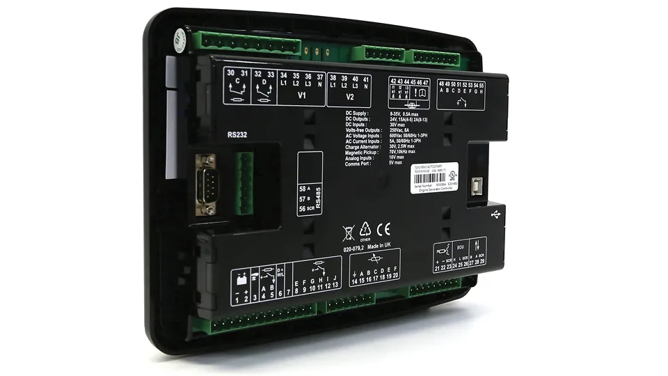
Image source: Bing (Web (fair-use with source credit))
The Ground Connection That Gets Missed
One terminal that first-time installers often overlook is the chassis ground stud located on the metal mounting bracket, not on the terminal block itself. The DSE 7310 MkII requires a direct earth connection from this stud to the generator frame ground. Skipping this connection causes erratic readings on the voltage sense inputs and can trigger false faults.
Manufacturer documentation specifies a minimum 4 mm² earth cable for this connection. Use a ring terminal and a star washer to ensure a solid bond.
Wiring Gauge Recommendations
The manual recommends specific wire gauges for each terminal group. Installers who ignore these recommendations often face intermittent faults or blown fuses.
| Terminal Group | Recommended Gauge | Maximum Length |
|---|---|---|
| DC Power (1-4) | 1.5 mm² (16 AWG) | 10 meters |
| Mains Sense (5-10) | 1.0 mm² (18 AWG) | 5 meters |
| Generator Sense (11-16) | 1.0 mm² (18 AWG) | 5 meters |
| Digital Inputs (17-20) | 0.75 mm² (20 AWG) | 10 meters |
| Relay Outputs (21-24) | 1.5 mm² (16 AWG) | 5 meters |
Using thinner wire on the relay outputs can cause voltage drop that prevents the fuel solenoid from engaging. Using thicker wire than needed on the sense inputs is fine but makes termination harder.
Common Terminal Numbering Mistake
The most frequent error reported in aggregate installation reviews involves misreading terminal numbers on the back panel. The numbers are laser-etched next to each terminal, but under poor lighting they can be hard to distinguish. Terminal 5 looks similar to terminal 6.
Terminal 11 looks similar to terminal 12.
One reliable trick: use a bright LED work light angled from the side rather than directly overhead. The side angle creates shadow contrast that makes the etched numbers readable. If you're still unsure, use a multimeter in continuity mode to confirm which terminal connects to which wire on the other end before applying power.
Navigating the LCD Menus: A Visual Walkthrough Screen by Screen
The DSE 7310 MkII menu system has a tree structure with four top-level branches. Each branch contains submenus for specific configuration categories. You navigate using the diamond buttons described earlier.
Entering Configuration Mode
You cannot change any parameters while the controller is running or in automatic mode. To enter configuration mode:
- Press and hold the Stop button for five seconds.
- The LCD shows "Enter Configuration Mode? Yes/No."
- Press the Enter button to confirm.
Once in configuration mode, the amber Configure LED lights up and stays lit. You now have full access to all parameters. The controller will not respond to start commands while in this mode.
The Four Main Menu Branches
From the top-level configuration screen, use the Up and Down buttons to scroll through these four options:
- Engine Setup: Crank time, rest time, number of start attempts, idle speed settings, and warm-up time.
- Mains Setup: Mains undervoltage and overvoltage thresholds, underfrequency and overfrequency limits, and mains failure detection delay.
- Protection Setup: Oil pressure alarm thresholds, coolant temperature limits, overspeed shutdown, and underfrequency shutdown.
- Input/Output Setup: Assign functions to each digital input and relay output. This is where you tell the controller what each physical terminal should do.
Each branch contains between 15 and 40 individual parameters. The manual lists every parameter with its default value, allowable range, and a description of what it controls.
How Parameters Are Displayed
When you select a parameter, the LCD shows its current value on the main line and its parameter number on a secondary line. For example:
"Oil Pressure Alarm
P-01 30 PSI"
The parameter number (P-01 in this example) matches the numbering in the manual. If you get lost, you can always find your position by cross-referencing the P-number with the printed parameter list.
To change a value:
- Press Enter to select the parameter.
- Use Up and Down to adjust the value.
- Press Enter to confirm the new value.
- Press Left to exit back to the parameter list.
The controller saves changes immediately. There is no separate save step.
The Hidden Fault Log Menu
One menu that does not appear in the default configuration mode is the fault log. You access it from the main operating screen, not from configuration mode.
- Press and hold the Enter button for three seconds while the controller is in automatic or manual mode.
- The LCD displays "Fault Log" and shows the last ten alarm events.
- Use Up and Down to scroll through recorded faults.
- Press Left to exit.
Each entry shows the fault type, the date and time it occurred, and the parameter value that triggered it. This is invaluable for diagnosing intermittent problems that don't happen while you're watching.
Returning to Normal Operation
When you finish configuring parameters, exit configuration mode by pressing and holding the Stop button for five seconds. The LCD asks "Exit Configuration Mode? Yes/No." Press Enter to confirm.
The amber Configure LED turns off, and the controller returns to its previous operating state.
Do not exit configuration mode while the controller is actively starting or stopping the generator. Wait for the sequence to complete, then exit.
Wiring the 7310 MkII: Matching the Diagram to Your Real-World Setup
Every DSE 7310 MkII installation is slightly different. Your generator might be single-phase or three-phase. Your transfer switch might be open transition or closed transition.
Your remote start signal might come from a building management system or a simple switch. The manual's wiring diagram covers the general case, but you need to adapt it to your specific equipment.
Start With the Power Supply
Before connecting anything else, wire the DC power supply. Terminal 1 gets battery positive through a 5 amp slow-blow fuse. Terminal 2 gets battery negative.
Do not connect the negative to chassis ground at this terminal; the chassis ground connection goes to the mounting stud mentioned earlier.
A common mistake here is using a fast-blow fuse instead of a slow-blow. The controller draws a brief inrush current when the battery is first connected. A fast-blow fuse rated at 5 amps can pop during this surge.
A slow-blow 5 amp fuse handles it fine.
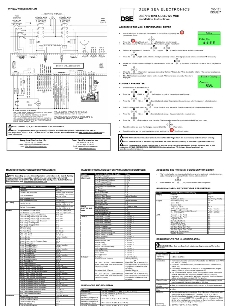
Image source: Bing (Web (fair-use with source credit))
Mains Sensing for Single-Phase vs. Three-Phase
The DSE 7310 MkII supports both single-phase and three-phase mains sensing. The wiring changes depending on which you have.
Single-phase wiring:
- Terminal 5 connects to mains live.
- Terminal 8 connects to mains neutral.
- Terminals 6, 7, 9, and 10 remain unused.
Three-phase wiring (4-wire wye):
- Terminal 5 connects to L1.
- Terminal 6 connects to L2.
- Terminal 7 connects to L3.
- Terminal 8 connects to neutral.
- Terminals 9 and 10 are unused.
- The controller calculates phase-to-neutral voltage internally.
Three-phase wiring (3-wire delta without neutral):
- Terminal 5 connects to L1.
- Terminal 6 connects to L2.
- Terminal 7 connects to L3.
- Terminal 8 is left unconnected.
- You must configure the controller for delta sensing in the mains setup menu.
If you wire a three-phase system as single-phase by mistake, the controller will show incorrect voltage readings and may never detect a genuine mains failure.
Generator Sensing Connections
The generator sensing terminals (11 through 16) follow the exact same pattern as the mains side. Wire them to the generator output terminals, not to the load side of the transfer switch. The controller needs to measure generator voltage before the switch closes to confirm the generator is ready.
One edge case that catches installers: if your generator has a three-phase output but only single-phase loads, wire all three generator sense terminals anyway. The controller uses all three phases to calculate frequency and phase rotation. Leaving one phase disconnected can cause a false phase-loss alarm.
Digital Inputs for Remote Functions
Terminals 17 through 20 accept dry contact inputs. Each input can be configured in the Input/Output Setup menu for a specific function.
Common configurations include:
- Terminal 17: Remote start signal from a building management system. A momentary contact closure tells the controller to start the generator.
- Terminal 18: Emergency stop. A normally closed contact that opens to stop the generator immediately.
- Terminal 19: Oil pressure switch. A normally open contact that closes when oil pressure rises above the configured threshold.
- Terminal 20: Coolant level switch. A normally closed contact that opens when coolant level drops below the sensor.
The manual specifies that each digital input should be wired with 0.75 mm² twisted pair cable to reduce electrical noise pickup. Long runs near heavy motor cables can induce false signals.
Configuring Protection Settings Without Blowing Anything Up
Protection settings are where a wrong number can cost you a generator. Set thresholds too tight and the controller shuts down on every minor fluctuation. Set them too loose and you let the generator run itself to failure.
The manual provides default values. You need to adjust them for your specific engine and application.
Oil Pressure Alarm Thresholds
The oil pressure alarm protects the engine from running with inadequate lubrication. The default setting in the manual is 15 PSI for most diesel generator engines. That works for many installations, but it depends on your engine's normal oil pressure at operating temperature.
Check your engine manual for the normal oil pressure range at idle and at full load. Set the alarm threshold 5 to 10 PSI below the normal idle pressure. For example, if your engine runs 30 PSI at idle, set the alarm to 20 PSI.
A startup delay of 15 seconds is standard. This gives oil pressure time to build before the controller checks the alarm condition. Adjust this if your engine takes longer to build pressure in cold weather.
Coolant Temperature Limits
High coolant temperature is the second most common shutdown cause. The default high temperature alarm is usually around 95 degrees Celsius for water-cooled engines. That's reasonable for most applications, but check your specific engine's rated maximum operating temperature.
Set the alarm 5 to 10 degrees below the engine's maximum safe temperature. This gives you a buffer before critical damage occurs. Do not set it lower than 85 degrees unless you have a specific reason, because normal operating temperature on a loaded generator often reaches 85 to 90 degrees.
Set the shutdown temperature to the engine's actual maximum allowable temperature, not the alarm temperature. The alarm gives you a warning and time to respond. The shutdown stops the engine before damage.
Overspeed and Underfrequency Shutdown
Overspeed protection prevents the engine from self-destructing if the governor fails. The default setting is typically 10 percent above the nominal frequency. For a 50 Hz system, that's 55 Hz.
For a 60 Hz system, that's 66 Hz. These are safe defaults for most engines.
Underfrequency shutdown prevents the generator from supplying power at a frequency too low for connected equipment. The default is typically 5 percent below nominal. For 50 Hz that is 47.5 Hz.
For 60 Hz that is 57 Hz. This protects sensitive loads like computers and variable frequency drives.
Never disable overspeed or underfrequency protection. Aggregate user reports from generator service companies show that disabled frequency protection is a leading cause of generator damage during governor failures.
Voltage Protection Settings
The mains and generator voltage protection settings have separate thresholds. The default limits are typically plus 10 percent and minus 15 percent from nominal. For a 230 V system, that is 253 V high and 195 V low.
These are reasonable for most utility grids.
If your site has a stable utility supply, you can set tighter limits to detect problems faster. If your site has frequent minor voltage dips from the grid, loosen the thresholds slightly to avoid nuisance trips. The manual recommends adjusting in 5 volt increments until you find the sweet spot.
The Power of Delays
Every protection parameter in the DSE 7310 MkII has a delay setting. This is the time the controller waits before triggering an alarm or shutdown. Delay settings prevent momentary fluctuations from causing unnecessary shutdowns.
A good rule of thumb is 5 seconds for voltage and frequency alarms, and 10 seconds for oil pressure and coolant temperature alarms. Shorten the delay for critical equipment that cannot tolerate even brief excursions. Lengthen the delay for non-critical applications where a momentary dip is acceptable.
Testing Your Protection Settings
After you set all protection parameters, test them before putting the generator into automatic service.
- Start the generator manually.
- Monitor the oil pressure and coolant temperature readings on the LCD.
- Simulate a fault by temporarily lowering the oil pressure alarm threshold below the current reading. The controller should show a fault within the delay time.
- Raise the threshold back to your intended setting.
- Test the mains failure function by disconnecting the mains sense voltage. The controller should start the generator after the configured mains failure delay.
Never skip this testing step. It confirms your wiring and settings are correct before the generator is called upon in an actual outage.
Common Visual Mistakes That Trip Up First-Time Users
Even experienced electricians make predictable mistakes with the DSE 7310 MkII. Knowing these upfront saves you troubleshooting time.
Confusing the Generator and Mains Sense Terminals
The most common wiring error is swapping the generator sense wires with the mains sense wires. Both terminal blocks look identical. Both use the same numbering pattern.
If you wire mains voltage to the generator sense terminals by mistake, the controller reads the wrong voltage and may refuse to start or may show a permanent "mains failure" condition.
Double-check your wiring by comparing the labels on the wires to the terminal numbers before applying power. A quick continuity check between the generator output and terminals 11 through 16 confirms correct connections.
Forgetting to Remove Jumper Links
Some controllers ship with jumper links installed on certain terminals for factory testing. These jumpers can remain in place if the installer does not check. If jumpers exist on the mains or generator sense terminals, they create short circuits that damage the controller when power is applied.
Inspect all terminals visually before wiring. Remove any jumpers you find. The manual shows which terminals may have jumpers in its pre-installation inspection section.
Pressing Buttons Too Quickly
The DSE 7310 MkII firmware has a debounce algorithm that filters out rapid button presses. If you press the navigation buttons faster than one press per 200 milliseconds, the controller may miss some presses. This leads to skipped menu items or parameters that don't change.
Press each button deliberately and wait for the LCD to update before pressing again. Slow is fast when configuring these controllers.
Misreading the LCD in Direct Sunlight
The LCD screen on the DSE 7310 MkII is readable indoors but washes out in direct sunlight. If you are installing the controller outdoors or in a bright engine room, you may struggle to read parameter values.
Angle the front panel away from the light source or use a portable shade. Do not rely on reading the screen in direct sunlight for critical parameter entry. Wait for shade or move the unit temporarily.
Mixing Up AC and DC Terminals
Terminal 1 and 2 are DC battery power. Terminals 5 through 16 are AC voltage sensing. A miswire that applies AC to the DC terminals can destroy the power supply section of the controller within seconds.
The manual labels each terminal group clearly, but under poor lighting or rushed conditions, the groups can look similar. Use a multimeter to verify all wires before connecting to the controller. This takes two minutes and prevents a costly replacement.
Troubleshooting with Your Eyes: What the Display Is Telling You
When something goes wrong, the DSE 7310 MkII tells you what happened. You just need to know how to read the clues.
The Fault Screen
When a fault occurs, the LCD switches from the normal operating display to a fault screen showing the alarm description. The red Fault LED lights up. The description is plain text, not a code.
You will see messages like "Mains Under Voltage," "Generator Over Frequency," "Low Oil Pressure," or "Engine Fail to Start."
Read the message carefully. It tells you exactly which parameter is out of range. Do not clear the fault without noting the message first.
Once you press Enter to acknowledge the alarm, the message disappears, and you have to check the fault log to see it again.
Using the Fault Log
The fault log stores the last ten events. Access it by holding the Enter button for three seconds from any operating screen. Each entry shows the fault type, the date and time, and the parameter value that triggered it.
If you have a recurring fault, check the log for patterns. Does the fault always happen at the same time of day? Does it always involve the same parameter?
These patterns help you diagnose wiring issues, sensor drift, or environmental factors.
What Flashing LEDs Mean
Flashing LEDs indicate the controller is in a transition state. Here are the most common flashing patterns and what they mean:
- Flashing green Mains Available: The controller is measuring the mains voltage and waiting for it to stabilize within configured limits.
- Flashing green Generator Available: The generator is running but its output voltage or frequency has not yet reached the configured thresholds.
- Flashing amber Generator Running: The controller is in the start sequence. The engine is cranking but has not yet started.
- Flashing red Fault: A new fault has occurred and has not been acknowledged. Press Enter to acknowledge and change the LED to solid.
If a flashing LED never becomes solid after the expected time, the condition is not being met. Investigate the corresponding system.
The "Engine Fail to Start" Message
This is the most common fault message on the DSE 7310 MkII. It means the controller attempted to start the engine the configured number of times without success. The default is typically three attempts.
When you see this message, check these items in order:
- Is there fuel in the tank?
- Is the battery voltage above 12.4 V for a 12 V system or 24.8 V for a 24 V system?
- Is the fuel solenoid getting power from the controller? Test by measuring voltage at the solenoid wire during a start attempt.
- Is the starter motor engaging? Listen for the cranking sound.
- Is the engine cranking speed sufficient? The controller may not detect crank speed if the battery is weak.
The fault log shows how long each start attempt lasted. If the crank time was only two seconds, the battery is likely weak. If the crank time was the full configured duration, the fuel system is likely the problem.
The "Mains Under Voltage" Message
This message appears when the mains voltage drops below the configured threshold for longer than the configured delay. It can indicate a genuine utility outage or a wiring problem.
Check the mains sense wiring first. Measure the voltage at terminals 5, 6, 7, and 8 with a multimeter. If you read correct voltage but the controller shows under voltage, check the wiring for loose connections or corrosion.
A loose neutral connection is a common cause of false under voltage readings.
If the wiring is correct and the utility is stable, the threshold may be set too high. Increase the undervoltage threshold by 5 volts and see if the fault clears.
Maintenance and Long-Term Care for Your Controller
The DSE 7310 MkII requires minimal maintenance, but a few simple steps keep it reliable for years.
Keep the Front Panel Clean
Dust and grime can obscure the LEDs and make the LCD hard to read. Wipe the front panel with a soft, dry cloth every few months. Do not use solvents or abrasive cleaners.
They can damage the plastic lens and the button seals.
Check Terminal Tightness Annually
Vibration from the generator can loosen terminal screws over time. Once a year, power down the controller and check that every terminal screw is snug. Do not overtighten.
A torque of 0.5 Nm is sufficient for most terminals, equivalent to finger-tight plus a quarter turn.
Pay special attention to the battery power terminals. Loose battery connections cause intermittent resets and erratic behavior.
Inspect the Fuse
The 5 amp slow-blow fuse in the battery positive line protects the controller from damage. Inspect it annually for signs of corrosion or discoloration. Replace it at the first sign of damage.
Keep a spare fuse in the generator enclosure.
Update Firmware When Necessary
Deep Sea Electronics periodically releases firmware updates that add features or fix bugs. You can check the current version by looking at the LCD during startup or by navigating to the information screen in the menu.
Updating firmware requires the DSE Configuration Suite software and a USB cable. The process takes about 15 minutes. Only update firmware if the release notes describe a fix or feature you need.
Do not update a working system unnecessarily.
Battery Maintenance
The controller draws a small current from the battery even when idle. If the generator sits unused for months, the battery can discharge below the controller's minimum operating voltage of 8 V for a 12 V system.
Use a battery maintainer or start the generator monthly to keep the battery charged. A fully discharged battery that remains connected to the controller can cause the controller to behave erratically or lose its parameter settings.
Frequently Asked Questions
Can I download the DSE 7310 MkII manual online?
Yes. Deep Sea Electronics provides the manual as a free PDF on their official website. Search for "DSE 7310 MkII manual" on their support page.
The PDF includes all wiring diagrams, parameter lists, and configuration instructions the same as the printed version.
What is the difference between the DSE 7310 and the DSE 7310 MkII?
The MkII version has a redesigned front panel with improved button feel and a brighter LCD. Internally, the MkII supports more configurable parameters and slightly faster processing. Wiring is nearly identical.
If you have a MkII, use the MkII manual specifically. The original manual has different parameter numbers.
How many start attempts does the DSE 7310 MkII make by default?
The default is three start attempts. Each attempt lasts the configured crank time (typically 10 seconds), followed by a rest period (typically 10 seconds). If the engine does not start after three attempts, the controller shows "Engine Fail to Start" and locks out further attempts until the fault is acknowledged.
Can I use the DSE 7310 MkII with a single-phase generator?
Yes. The controller supports single-phase and three-phase systems. For single-phase, wire only the L1 and neutral terminals on both the mains and generator sense blocks.
Configure the controller for single-phase operation in the mains setup menu.
What does it mean when the Fault LED is flashing but the LCD shows no message?
A flashing Fault LED indicates a new unacknowledged alarm. Press the Enter button once to acknowledge it. The LED changes to solid red, and the LCD shows the fault description.
If the LCD still shows no message after acknowledging, check the fault log by holding the Enter button for three seconds.
How do I reset the DSE 7310 MkII to factory defaults?
Enter configuration mode by holding the Stop button for five seconds. Navigate to the system setup menu. Select "Reset to Defaults" and confirm.
This clears all custom parameters and restores factory settings. Write down your custom settings before resetting, because the controller returns to default values for all parameters.

Similar Posts